Nodela
Download the interface here, and check out the native app for OSX.
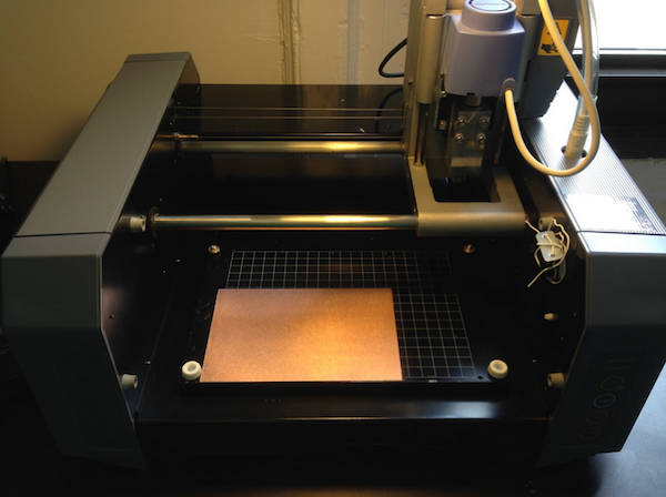
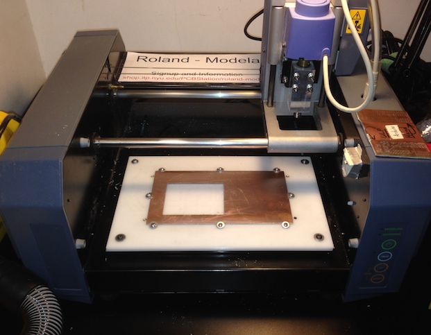
The Roland-Modela is a discontinued micro-milling machine, and students at ITP used it to mill PCBs from copper clad plates. It’s an OK machine, but its software package is terrible.
I made a simple interface using Javascript, and designed a new bed from delrin, and now I can cut straight from an Eagle file without breaking bits.
The Interface
Nodela allows you to jog the head around, in order to select your cut’s origin (impossible until recently). It also loads preset speed and plunge values for different bits, so that each bit is used at it’s most optimal settings.
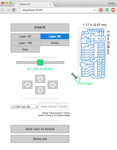
To load your file, simply drag the Eagle .brd file onto the interface, and it will parse our all the layers that contain toolpath lines (drawn with WIRES). Then it’s just a matter of selecting the correct layer and bit size before pressing print!
Links and Tutorials
The software can be found on GitHub. Check out the README for installation instructions and getting in running.
The FAQ for the Roland-Modela and interface can be found on ITP’s shop website. Here is a direct link to the Modela’s page.
I have also recorded to video tutorials on using the Modela. The first is on how to prepare your Eagle file to be milled, and the second is a walkthrough of cutting that same file.
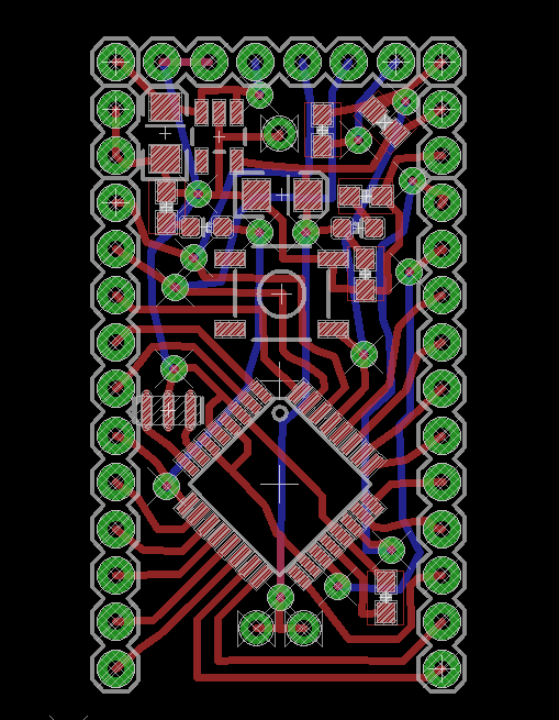
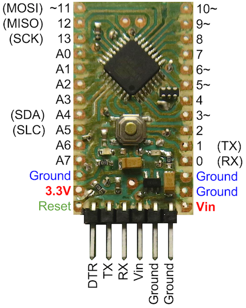
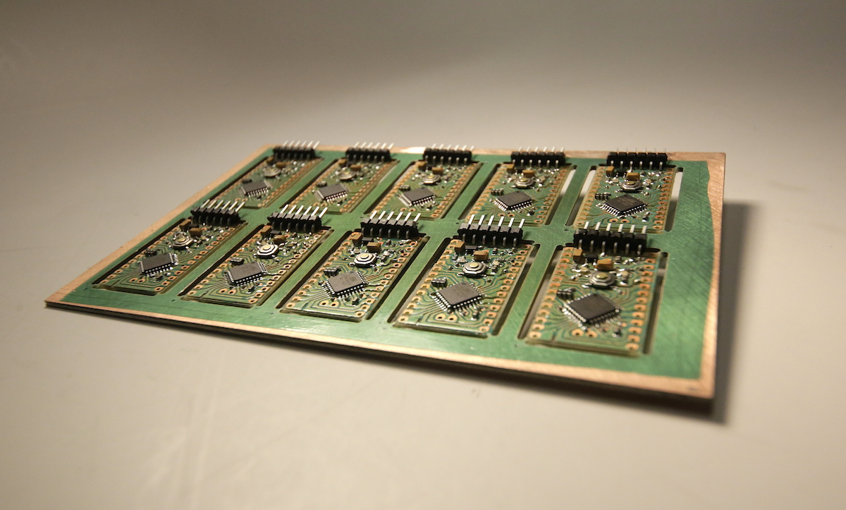
Panel of Arduino Minis
Here are some pictures of my attempt at making a panel of 10 Arduino Mini’s of my own design. You can find the pin layout, board files, and other documentation on GitHub;
These 10 boards were created within one day at ITP. I milled the panel in the morning, cleaned and added solder mask in the afternoon, and assembled at night. It was a long process, but I’ve never been able to make 10 boards of such quality and in such a short amount of time.
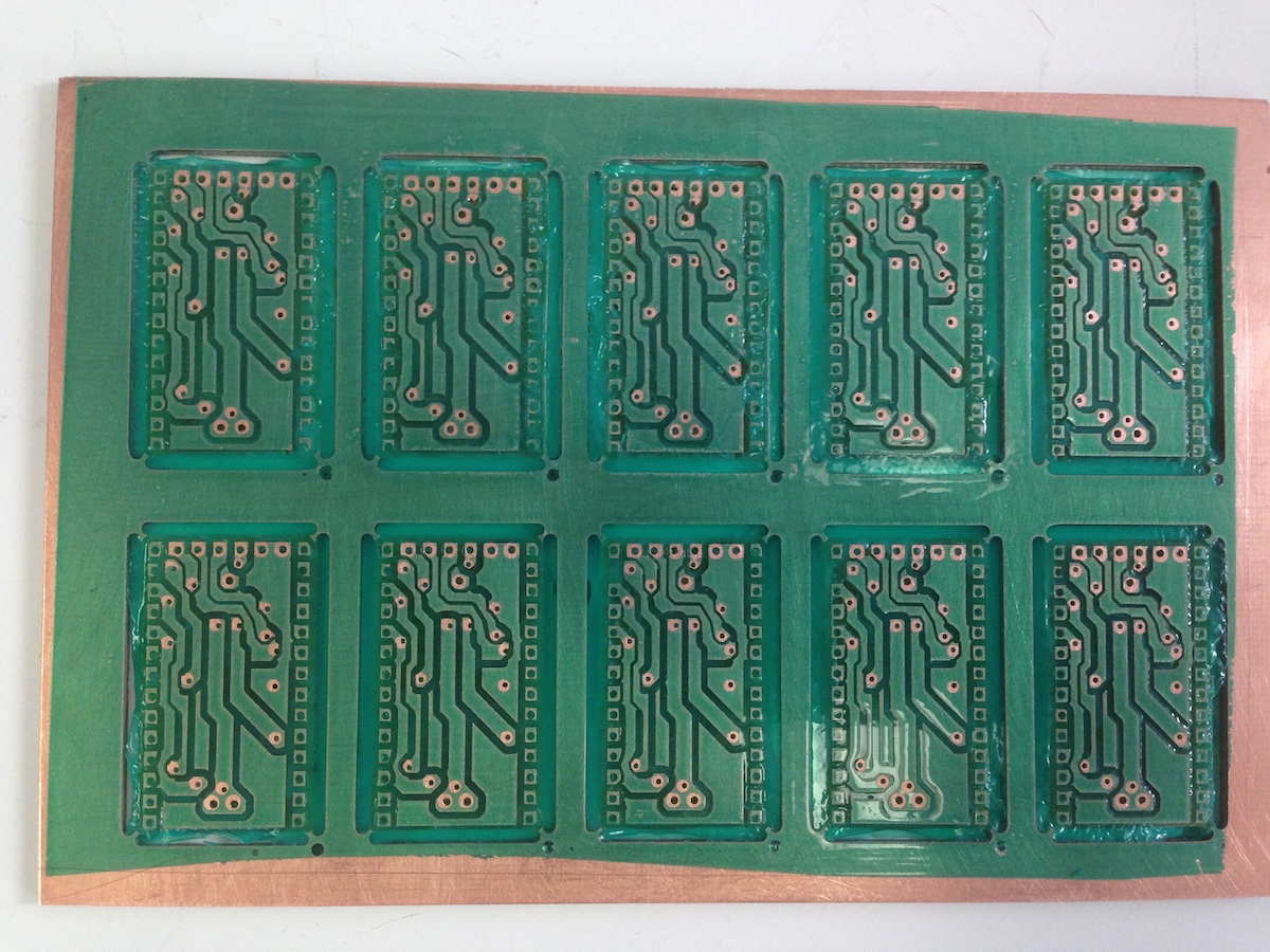
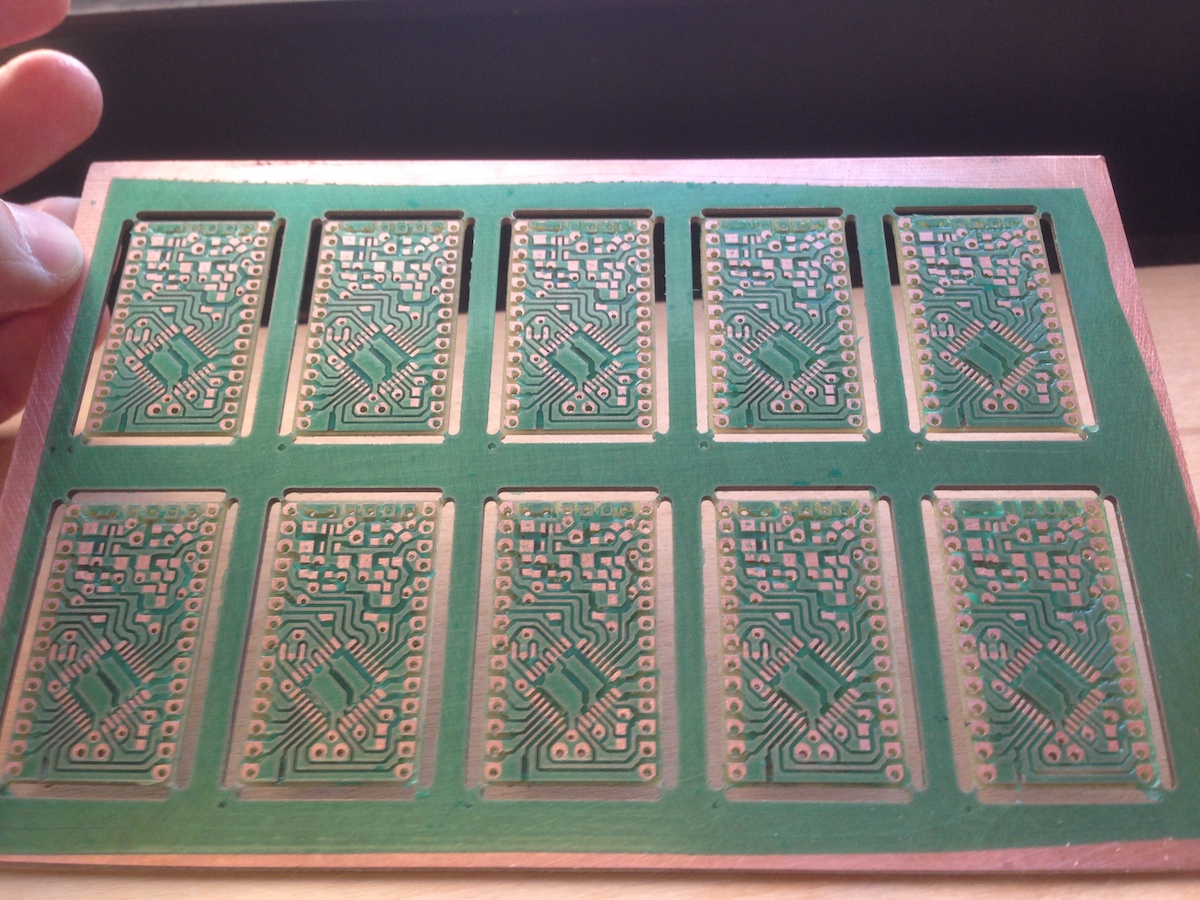
Solder Mask Results
I’ve been using Dynamask dry-film solder mask, and it’s made populating boards much easier. I’ve documented the process a bit in my blog, and below are some pictures of my panel after milling and applying the solder mask.
Top layer:

Bottom layer:
Pretty picture:
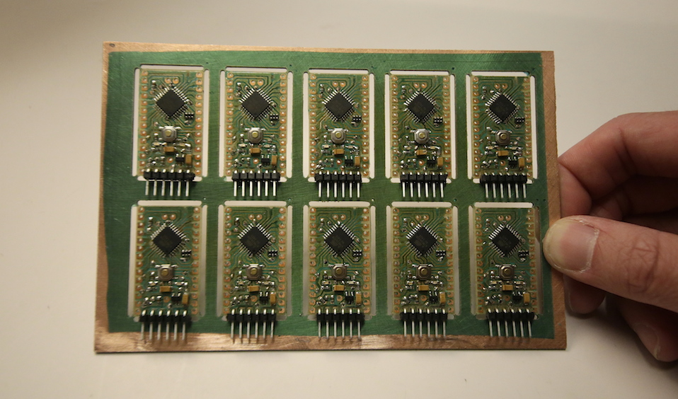
Results after Assembly
I used ITP’s manual pick-and-place machine to lay out the solder and place each component. I then reflowed using a heat gun, and finally soldered together all the vias.
The vias are what takes the longest, and greatly restrict your design. I use a thin piece of wire to connect the top and bottom of the PCB, then solder each side. This means that there can not be any vias underneath any component or IC, and that they need a considerable amount of space to allow the solder to melt with causing any shorts.
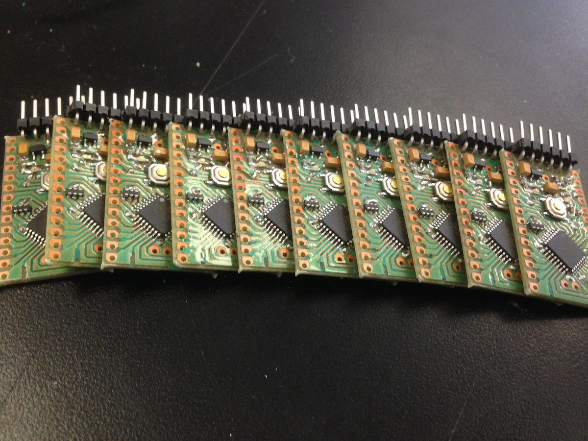
Broken Out Boards
Bootloaded and test, they all work!
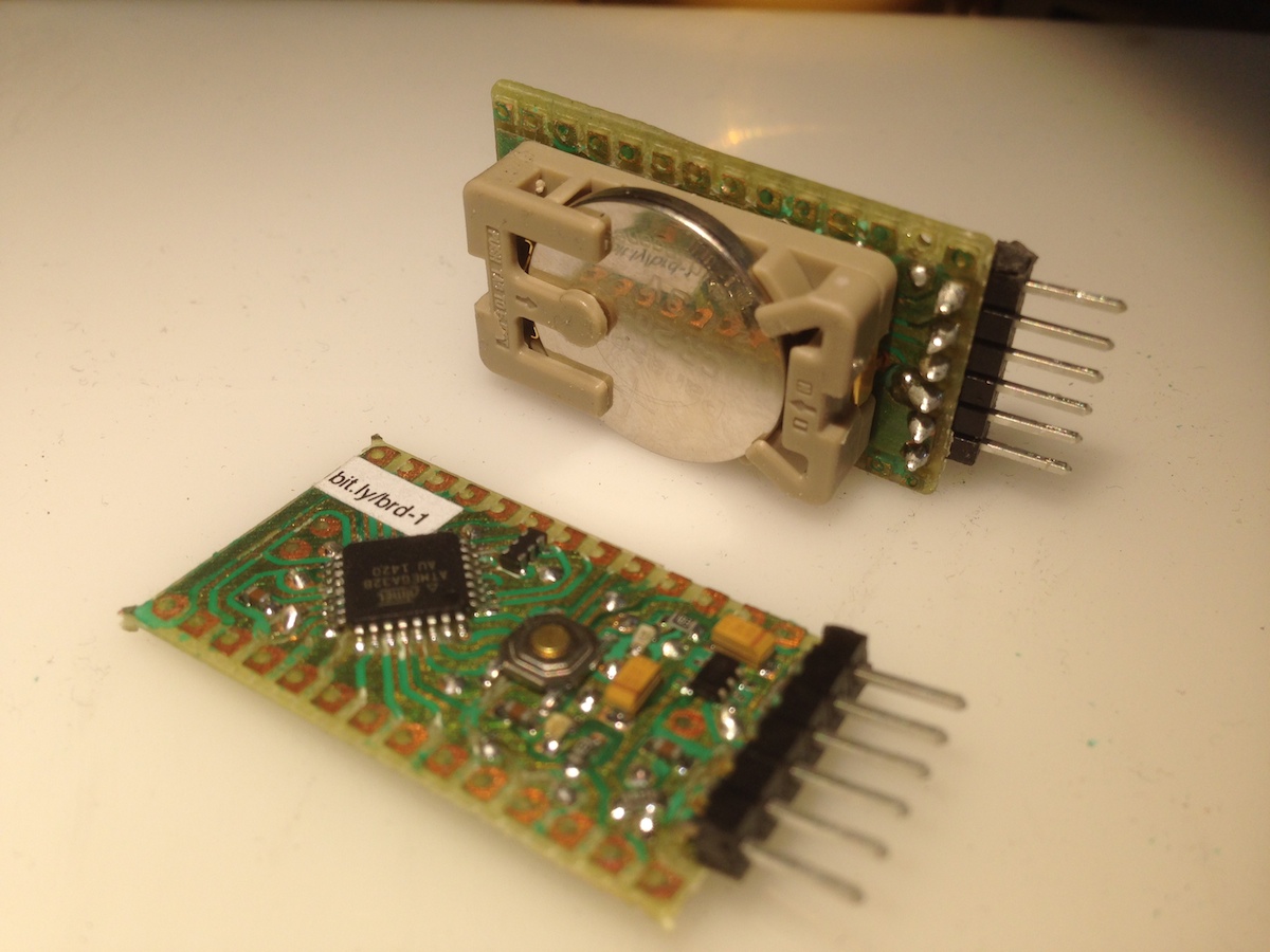
I decided to add the option of soldering a coin-cell battery holder onto the bottom. Here you can see one attached:
HARDWARE
automation